Mechnical Vacuum Boosters
Aakash Engineering Works – AEW
MECHANICAL VACUUM BOOSTERS
Engineering • Performance • Reliability • Process Efficiency
PRODUCT & APPLICATION CATALOG
Mechanical Vacuum Booster Technology
Contents
- Product Overview
- Understanding Vacuum & Key Terms
- Operating Principle
- Construction & Major Components
- How a Booster Improves a Vacuum System
- Operating Modes & System Arrangements
- Booster Start-Up, Cut-In & Control
- Pre-Condenser and Post-Condenser Installation Concepts
- Performance Characteristics
- Application Areas
- Industry Applications
- Advantages of AEW Mechanical Vacuum Boosters
- Vacuum System Selection Methodology
- Process Load Assessment
- Pipework, Condensers & System Conductance
- Installation Guidelines
- Operation & Control Philosophy
- Maintenance & Reliability
- Troubleshooting Guide
- Safety & Good Engineering Practice
- AEW Technical Data Section
- Application Selection Checklist
- Customer Technical Enquiry Sheet
- Glossary of Vacuum Terminology
- Why Choose AEW Mechanical Vacuum Booster System?
1. AEW Mechanical Vacuum Booster — Product Overview
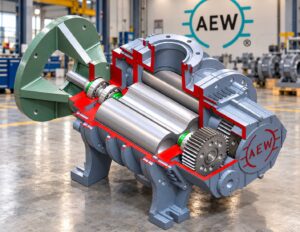
AEW Mechanical Vacuum Boosters are positive-displacement vacuum machines designed to increase pumping speed and improve the attainable working vacuum of a vacuum system when operated with an appropriately selected backing or fore pump. Their principal value is not simply to provide additional displacement, but to improve the overall performance of a complete vacuum system in the pressure region where the existing pump becomes less effective.
The booster is particularly useful where high gas/vapour throughput, faster pump-down, lower process pressure, reduced process temperature, vapour recovery or improved utilization of an existing vacuum pump is required.
| Engineering principle A mechanical vacuum booster is normally applied as part of a vacuum pumping system. The booster and backing pump must be selected as a matched combination based on process pressure, gas/vapour load, required pumping speed, allowable differential pressure and the required ultimate/working vacuum. |
What the booster does
- Increases effective pumping speed in the operating pressure region where the backing pump alone becomes less effective.
- Improves the working vacuum that can be achieved by a suitable backing-pump combination.
- Handles gas and vapour loads without using a pumping/sealing fluid in the pumping chamber.
- Can reduce pump-down time and increase process throughput when correctly sized and integrated.
- Can reduce dependence on large conventional backing pumps or multi-stage ejector arrangements in suitable applications.
- Can be integrated with existing vacuum equipment such as rotary pumps, liquid-ring/water-ring pumps, ejector systems and other suitable backing pumps.
Product philosophy
AEW booster packages should be engineered around the process rather than selected only by nominal displacement. Correct selection considers the required pressure, total process load, condenser arrangement, leakage/outgassing, backing-pump characteristics, piping conductance and allowable booster differential pressure.
2. Understanding Vacuum
Vacuum is a pressure below atmospheric pressure. A vacuum system produces this condition by removing gas and/or vapour from an enclosed volume. As more mass is removed, the absolute pressure inside the system decreases.
Vacuum engineering is fundamentally a pressure-and-load problem. The required pump is governed not only by the final pressure, but also by how much gas or vapour must be removed and how quickly the process must reach or maintain the specified pressure.
Vacuum ranges
| Region | Approximate pressure range | Typical engineering relevance |
| Coarse vacuum | ~10 to 760 Torr | Drying, filtration, evaporation and general process vacuum |
| Medium vacuum | ~0.001 to 10 Torr | Deeper drying, distillation and many process applications |
| High/fine vacuum | Lower than the medium-vacuum region | Specialized process, thermal, metallurgical and laboratory applications |
The exact pressure range of a given process should always be stated in absolute pressure units and evaluated together with the gas/vapour load and required pumping speed.
Essential vacuum terms
| Term | Meaning |
| Absolute pressure | Pressure measured from absolute zero pressure; this is the preferred basis for vacuum-system engineering. |
| Torr | A vacuum pressure unit; approximately equivalent to 1 mmHg. |
| Pumping speed | Volumetric rate at which a pump removes gas at a specified pressure and location, commonly expressed in m³/h or L/min. |
| Throughput | Quantity of gas handled per unit time expressed in pressure-volume/time terms or as mass flow, depending on the application. |
| Ultimate / blank-off vacuum | The limiting pressure approached by a pump under defined test conditions when useful pumping capacity approaches zero. |
| Backing / fore pump | The pump that receives the booster discharge and ultimately exhausts the gas from the system. |
| Staging ratio | Ratio between booster pumping capacity and the capacity of the backing pump in the applicable operating arrangement. |
| Compression ratio | Ratio of booster discharge absolute pressure to booster inlet absolute pressure. |
| Differential pressure | Pressure difference between booster discharge and booster suction. It is a critical operating limitation. |
| Pump-down time | Time required to evacuate a system from a defined starting pressure to a specified pressure. |
| Leak load | Gas entering the system through unintended leakage paths. |
| Outgassing | Gas/vapour released by process materials, surfaces, moisture, seals or other internal sources. |
3. Operating Principle
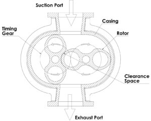
AEW Mechanical Vacuum Boosters use two figure-eight-shaped lobes/rotors rotating in opposite directions inside a precisely machined casing. The rotors do not contact each other or the casing during normal operation; the required clearances are maintained through accurate rotor geometry, shaft alignment and timing gears.
As a rotor lobe passes the suction port, it traps a defined quantity of gas. The trapped gas is transported around the casing from the suction side to the discharge side. The process is repeated continuously as the rotors turn.
- Gas enters the booster through the suction port.
- Rotating lobes isolate pockets of gas within the casing.
- The trapped gas is carried around the casing toward the discharge port.
- Timing gears maintain the relative angular position of the rotors.
- Gas leaves the booster at a higher absolute pressure and is handled by the backing pump.
- Continuous repetition of this displacement action produces high volumetric pumping capacity.
| Why timing gears matter Because the rotors operate with finite internal clearances, accurate synchronization is essential. The timing system maintains the rotor-to-rotor relationship and prevents contact during normal operation while preserving high volumetric efficiency. |
Positive-displacement behaviour
The booster behaves primarily as a positive-displacement machine. Its displacement is closely related to rotor geometry and rotational speed, while the actual system pumping speed is influenced by pressure, internal slip, gas properties, temperature, piping conductance and the backing-pump combination.
Dry pumping
The pumping chamber is designed for dry gas/vapour handling; no pumping liquid is intentionally introduced into the rotor chamber to create the pumping action. This is particularly valuable where process-vapour contamination must be minimized or where condensable and non-condensable loads are present.
| Important distinction “Oil-free pumping chamber” does not mean the complete machine has no lubricants. Bearings, timing gears or other drive components always require lubrication which should be scheduled as per AEW manual. The final AEW model datasheet should define lubrication points, oil quantity and recommended lubricant. |
4. Construction & Major Components
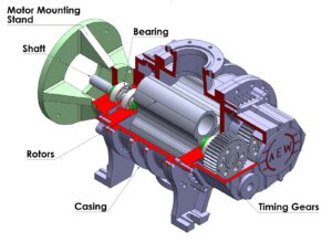
A professional vacuum-booster package should be understood as a precision mechanical assembly rather than only a casing and rotor set. The principal functional elements are described below. For Exact materials, dimensions, seal arrangements and cooling configurations, Please Connect with AEW team.
| Component | Engineering function |
| Casing | Forms the controlled gas path and houses the rotors. Precision geometry and stiffness are essential to maintain clearances. |
| Twin rotors / lobes | Positive-displacement elements that trap and transport the gas from suction to discharge. |
| Timing gears | Synchronize the rotors and maintain the designed phase relationship. |
| Shafts / integrated rotor shafts | Transmit torque while maintaining rotor position and alignment. |
| Bearings | Support the rotating assemblies and control shaft position. |
| Shaft sealing arrangement | Limits gas migration from the process chamber toward the drive/bearing zones; construction may vary by design. |
| Lubrication system | Provides lubrication to components that require it, typically outside the pumping chamber. |
| Drive system | Motor and transmission arrangement selected for the required speed and power. |
| Cooling arrangement | May be air-cooled or water-cooled depending on model and application. |
| Base / skid | Supports the machine and, in packaged systems, associated piping, valves, instrumentation and controls. |
Seal configurations
Mechanical vacuum boosters can be engineered in different sealing configurations, including lip-seal and seal-less arrangements. Seal selection should be based on process vapour composition, temperature, contamination sensitivity, required vacuum level and maintenance philosophy.
For applications involving volatile solvents, hydrocarbons, organic vapours or especially clean/high-vacuum service, the appropriate AEW construction and sealing arrangement should be confirmed during technical selection.
5. How the Booster Improves a Vacuum System
Many conventional vacuum pumps have a useful operating range in which pumping speed is high. As pressure is reduced toward the limiting capability of the pump, its effective pumping speed can fall substantially. Installing a mechanical booster in the correct pressure region can recover high pumping capacity where the backing pump alone is no longer efficient.
The booster therefore works with the backing pump rather than replacing it in the majority of compression-mode applications.
Typical arrangement
| Typical vacuum train PROCESS / VESSEL → CONDENSER or TRAP → AEW BOOSTER → BACKING / FORE PUMP → EXHAUST |
Depending on the process, the booster may be positioned upstream or downstream of the condenser. The correct location is a process-design decision based on vapour load, condensation temperature, desired pressure in each process zone and the acceptable load on the booster.
Why the combination works
- The backing pump performs the initial roughing and handles the booster discharge.
- The booster provides high volumetric pumping speed in the pressure range where the backing pump is less effective.
- The booster compresses the gas before it reaches the backing pump, improving the effective operating conditions for the backing pump.
- The combined system can achieve a lower working pressure and/or substantially higher throughput than the backing pump alone, subject to correct selection.
Illustrative engineering relationship
For a gas load expressed as mass flow, the required volumetric pumping speed rises as absolute pressure falls. This is why a process requiring the same mass-flow removal at a much lower pressure can require a much higher volumetric pumping speed.
| Selection lesson Do not select a vacuum pump by displacement alone. Always state the required working pressure, gas/vapour load, temperature, pump-down time and backing-pump arrangement. |
6. Operating Modes & System Arrangements
6.1 Compression mode
Compression mode is the general arrangement for improving working vacuum and pumping speed. The booster is installed in series with a backing pump whose rated capacity is normally lower than the booster capacity.
Two important ratios are used:
- Staging ratio = booster capacity ÷ backing-pump capacity, evaluated on the same basis.
- Compression ratio = booster discharge absolute pressure ÷ booster inlet absolute pressure.
6.2 Transport mode
In transport mode, the booster and backing pump are operated with a staging ratio close to unity. The objective is primarily to improve throughput and ultimate pressure behaviour rather than to obtain a large compression ratio.
6.3 Multi-stage booster systems
Two or more booster stages can be arranged in series when very high pumping speed is required at low pressure. The multi-staging for applications extending toward approximately 0.001 Torr, provided the complete system is properly engineered.
6.4 Integration with existing pumps
Suitable combinations can include rotary vacuum pumps, rotary piston pumps, liquid-ring/water-ring pumps, water ejectors, steam ejectors and other compatible backing arrangements. The final vacuum is governed by the booster/backing-pump combination and the process load.
7. Booster Start-Up, Cut-In & Control
A conventional compression-mode booster should generally not be started directly against atmospheric pressure unless the machine and control arrangement are specifically designed for such operation. High differential pressure at start-up can create excessive power demand and heat generation.
Conventional pressure-switch / bypass arrangement
# Start the backing pump and evacuate the system.
# Allow system pressure to reach the specified booster cut-in pressure.
# Start or permit the booster to start when the pressure is within its permitted operating envelope.
# During pump-down, monitor suction pressure, discharge pressure, motor current, temperature and vibration.
# During shutdown, follow the specified sequence so that the booster is not exposed to an unacceptable differential pressure.
Bypass arrangement
A bypass line around the booster can be used for initial pump-down. This allows the backing pump to reduce the system pressure before the booster is brought into operation.
Variable-frequency / automatic-speed control
A suitable variable-frequency control arrangement can regulate booster speed according to system pressure and motor load. This can permit coordinated start-up, controlled acceleration and improved utilization of the booster over a wider operating range, subject to the approved motor and booster speed limits.
| Control objective The control system should protect the booster against excessive differential pressure, excessive motor current, overheating and operation outside the approved speed envelope. |
8. Pre-Condenser & Post-Condenser Installation Concepts
The location of the booster relative to the condenser can materially influence process performance. Two important configurations are commonly considered.
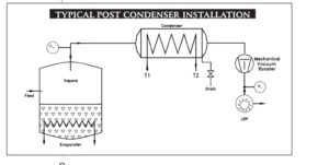
Post-condenser booster
The booster is installed downstream of the condenser and upstream of the backing pump. This arrangement can be advantageous when the condenser can remove a large portion of the vapour load before the booster. It is particularly relevant to drying and solvent-recovery processes where the condensate temperature and vapour pressure influence the attainable process pressure.
- Lower vapour load reaches the booster after effective condensation.
- The booster can provide additional pressure reduction after the main condensation duty.
- Useful when a process requires finer vacuum toward the end of a batch cycle.
- Can help improve product drying or final solvent removal in suitable applications.
Pre-condenser booster
The booster is installed between the process/evaporator and the condenser and therefore handles the process vapour before condensation. This configuration can be useful where the condenser temperature cannot be kept sufficiently low, where the condensable is a low-boiler, or where a higher vacuum is desired in the evaporating zone while retaining favourable pressure conditions for the condenser.
- Can create a lower pressure on the evaporator/process side.
- Can maintain a relatively higher pressure at the condenser side, supporting condensation.
- Can improve the separation between evaporation and condensation conditions.
- Requires careful evaluation of vapour temperature, condensability and booster material/seal compatibility.
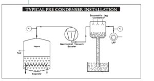
| Process-design rule The best booster location cannot be chosen from vacuum level alone. Evaluate vapour composition, condensation temperature, vapour pressure, heat load, desired evaporator pressure, condenser duty and booster differential pressure. |
9. Performance Characteristics
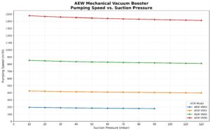
The performance of a mechanical vacuum booster is best represented by a pumping-speed-versus-pressure curve. The curve normally shows that the booster is not equally effective at every pressure. At high suction pressure, the booster may be limited by differential pressure and power. At lower pressure, its volumetric pumping capability becomes particularly valuable.
Typical behaviour
- High volumetric pumping capability at low absolute pressure.
- Very low internal friction relative to many conventional pumping mechanisms.
- High pumping speed can be obtained with comparatively low energy per unit of throughput in the appropriate pressure region.
- Actual system speed is lower than ideal displacement because of internal slip and system losses.
- The backing pump and booster must be evaluated as a combined system.
Model performance curve — AEW placeholder
 |
10. Application Areas
Mechanical vacuum boosters are suited to processes where higher pumping speed, improved vacuum, shorter cycle time, lower process temperature or dry vapour handling provides a measurable process benefit.
- Vacuum drying and tray drying
- Rotary vacuum drying
- Flash drying
- Vacuum distillation
- Solvent recovery
- Vacuum filtration
- Vacuum concentration / evaporation
- Vacuum crystallization
- Vacuum cooling / evaporative cooling
- Oil de-odourization
- Vacuum impregnation
- Sterilization processes
- Gas recirculation and pressure-loss compensation
- Degassing and refining
- Evaporation and sputtering
- Vacuum furnaces and thermal processing
- Heat treatment
- Sintering and brazing
- Electron-beam welding
- Ionic nitriding
- Tool coating
- Vacuum casting
- Metallization and roll metallization
- Semiconductor-related processing
- Vacuum and microwave tube manufacture
- Automotive and miniature lamp manufacture
- Space research and development applications
Drying applications
In vacuum drying, reducing absolute pressure lowers the boiling temperature of the volatile component. A properly engineered booster system can therefore support faster moisture or solvent removal while helping maintain product temperature at a controlled level.
Distillation & evaporation
Lower process pressure can permit evaporation or distillation at lower temperatures. This can be valuable for temperature-sensitive products and for high-boiling materials. A booster can also increase vapour-handling capacity and improve the operating conditions of the condenser/backing-pump system.
Solvent recovery
A dry booster can handle process vapour without introducing a pumping liquid into the gas stream. Where vapour recovery is required, the discharge side can be routed through appropriate condensers and collection equipment. Materials, seals and temperatures must be checked against the actual solvent.
Food & pharmaceutical processing
Dry pumping can be advantageous where contamination by sealing or motive fluid must be avoided. Hygiene, materials of construction, sealing, cleanability and applicable customer standards should nevertheless be reviewed separately for each installation.
11. Major Industries Served
| Industry | Typical vacuum duties |
| Chemical & process | Drying, evaporation, distillation, solvent recovery, filtration, crystallization |
| Pharmaceutical | Drying, solvent handling, concentration, sterilization and clean dry vacuum duties |
| Food processing | Drying, concentration, de-aeration and other dry vacuum processes |
| Oil & specialty products | De-odourization, filtration, drying and vacuum processing |
| Semiconductor / electronics | Vacuum processing, coating, metallization and thermal operations |
| Electrical & lighting | Lamp manufacture, tube production, vacuum impregnation and related processes |
| Industrial processing | Degassing, drying, heat treatment, vacuum casting and general process vacuum |
| Metallurgical / thermal | Vacuum furnaces, sintering, brazing, heat treatment, nitriding |
| Research & specialized systems | Vacuum development, controlled-atmosphere processes and gas recirculation |
12. Advantages of AEW Mechanical Vacuum Boosters
| Advantage | Customer benefit |
| Dry pumping | No pumping liquid is intentionally used in the pumping chamber, making the machine suitable for many gas/vapour applications. |
| High volumetric pumping speed | Designed to move large gas volumes efficiently in the appropriate low-pressure operating region. |
| Improved process vacuum | When correctly matched with a backing pump, the booster can extend the working vacuum capability of the system. |
| Reduced pump-down time | High pumping speed can reduce evacuation time, particularly in batch processes. |
| Energy-efficient system design | A booster/backing-pump combination can deliver higher pumping speed per unit of power than an oversized conventional pump in suitable applications. |
| Reduced back-streaming risk | Booster compression can raise the pressure at the backing-pump inlet and can reduce reverse migration of backing-pump fluid in suitable systems. |
| Low internal mechanical complexity | The pumping element has no reciprocating piston or suction/discharge valve in the gas path. |
| System integration | Can be added to existing vacuum systems when the process, pressure and mechanical interfaces are suitable. |
| Flexible control | Pressure switches, bypass arrangements and variable-frequency control can be used according to the required operating philosophy. |
| Vapour handling | Suitable designs can handle condensable and non-condensable loads; actual vapour compatibility must be verified for the application. |
13. Vacuum System Selection Methodology
The most important engineering step is to define the complete process load before selecting the booster. A vacuum system that is too small may fail to achieve the process condition; a system that is excessively large may increase capital cost, operating cost and control complexity.
Step 1 — Define the process vacuum
- Required operating pressure: ______ Torr absolute / ______ mbar absolute
- Required minimum pressure: ______ Torr absolute / ______ mbar absolute
- Normal operating pressure: ______ Torr absolute / ______ mbar absolute
- Pump-down starting pressure: ______
- Required pump-down time: ______ minutes
Step 2 — Define the process load
- Non-condensable gas load: ______ kg/h or ______ m³/h
- Water vapour load: ______ kg/h
- Solvent / process vapour load: ______ kg/h
- Air leakage load: ______
- Outgassing load: ______
- Other gas/vapour load: ______
Step 3 — Define temperatures
- Process temperature: ______ °C
- Condenser inlet temperature: ______ °C
- Condenser outlet temperature: ______ °C
- Cooling-water temperature: ______ °C
- Gas/vapour temperature at booster suction: ______ °C
Step 4 — Select the backing pump
The backing pump must be capable of receiving the booster discharge at the required throughput while remaining within its own pressure and temperature limits. The booster should never be selected independently of the backing pump.
Step 5 — Select booster size
Select the booster using the AEW model pumping-speed curve at the required suction pressure, allowable differential pressure, motor power and operating speed. Confirm the model against the required process load and pump-down duty.
Step 6 — Confirm mechanical and process compatibility
- Gas/vapour composition
- Condensability and possible liquid carryover
- Corrosiveness
- Temperature
- Solvent compatibility
- Seal material
- Materials of construction
- Cooling arrangement
- Flange size
- Motor and electrical supply
- Area classification / hazardous-area requirements where applicable
14. Process Load Assessment
A vacuum pump must remove the total gas/vapour load entering the system. There are three major load categories: plant air leakage, non-condensable process gases and condensable process vapours escaping the condenser. In real installations, outgassing and intentional gas injection may also need to be included.
Air leakage
Air leakage can be estimated by a pressure-rise or drop test. The system is evacuated to a defined pressure, isolated, and the rate of pressure rise is measured. This provides an estimate of the leakage load that the pumping system must continuously remove.
Condensable vapour load
Condensable vapours can dominate the load during parts of a process cycle. Condenser performance therefore has a direct impact on booster sizing. A booster located before the condenser may have to handle the full process vapour load; a post-condenser booster may see a much smaller residual load.
Non-condensable load
Dissolved gases, air ingress and other permanent gases may pass through the condenser and become the dominant load after condensation is established.
Illustrative load-to-speed relationship
For a gas load at a fixed temperature, the required volumetric pumping speed increases approximately in inverse proportion to absolute pressure. The supplied literature demonstrates this with the same air mass load at 100, 10 and 1 Torr, showing a tenfold increase in required volumetric speed each time the absolute pressure is reduced by a factor of ten.
15. Pipework, Condensers & System Conductance
The pipe connecting the process vessel, condenser, booster and backing pump is part of the vacuum system. Even an appropriately sized pump can underperform if the connecting pipe is too small, too long, poorly arranged or contains excessive restrictions.
Pipework considerations
- Use adequate diameter to maintain high conductance.
- Minimize unnecessary elbows, sudden contractions and restrictive valves.
- Keep the suction line as short and direct as practical.
- Provide suitable isolation and maintenance provisions.
- Prevent liquid traps where unwanted condensate accumulation can occur.
- Ensure the piping can withstand the applicable pressure, temperature and process chemistry.
- Select flange size from the actual required conductance rather than only matching the booster port.
Condensers and traps
Condensers and traps can protect the booster by removing condensable vapours before they reach the machine. However, the condenser itself introduces pressure drop and therefore must be included in the system pressure balance.
System pressure balance
| Think in terms of the complete system Process pressure → suction piping loss → condenser pressure loss → booster inlet → booster discharge → backing-pump inlet → backing-pump discharge. Every element affects the final result. |
16. Installation Guidelines
Mechanical installation
- Install the booster on a rigid, level support capable of carrying the operating weight and dynamic loads.
- Check shaft alignment and coupling alignment according to the AEW installation manual.
- Do not transmit external pipe loads to the booster casing.
- Provide adequate access for inspection, lubrication and service.
- Use suitable vibration isolation where required by the package design.
- Verify rotation direction before full-load operation.
Vacuum-side installation
- Clean all process piping before connection.
- Prevent foreign particles from entering the booster.
- Provide appropriate inlet filtration/knockout protection where required.
- Install isolation valves and bypass arrangements according to the approved P&ID.
- Ensure the suction line is adequately supported and free of excessive restriction.
Electrical installation
- Verify motor voltage, frequency and power rating.
- Provide appropriate overload and short-circuit protection.
- Where VFD control is used, set minimum/maximum speed limits according to AEW instructions.
- Interlock booster operation with pressure, temperature and motor protection where required.
- Ensure correct earthing and electrical safety.
17. Operation & Control Philosophy
Recommended operating sequence
- Confirm the system is mechanically complete and all required valves are in the correct position.
- Confirm oil/lubricant levels in all components that require lubrication.
- Confirm cooling arrangements are available if required.
- Start the backing/fore pump or place the system in the approved automatic sequence.
- Reach the specified booster cut-in pressure before applying full booster load unless an approved automatic-speed arrangement is provided.
- Start the booster and monitor pressure, current, temperature, vibration and noise.
- During steady operation, verify that the operating point remains inside the AEW performance envelope.
- At shutdown, follow the approved sequence to prevent excessive differential pressure or reverse flow.
Instrumentation recommended for a professional package
- Suction pressure transmitter/gauge
- Discharge / backing pressure indication
- Motor current indication
- Booster temperature monitoring where applicable
- Lubrication level/pressure indication where applicable
- Vibration monitoring for critical installations
- Emergency stop
- Interlocked pressure switch or programmable pressure control
- Alarm and trip signals for abnormal operating conditions
18. Maintenance & Reliability
The rotor chamber is designed for low-contact dry pumping, so there are no internal rubbing vanes or reciprocating pistons in the pumping chamber. Nevertheless, the machine remains a precision rotating assembly and requires disciplined maintenance.
Routine checks
- Check lubrication level and condition at the intervals specified by AEW.
- Inspect for abnormal vibration or noise.
- Monitor bearing and casing temperatures where instrumentation is provided.
- Check shaft seals for leakage where applicable.
- Inspect coupling, belt or transmission elements as applicable.
- Keep inlet filters, separators and condensers clean.
- Check electrical connections and motor condition.
- Review operating trends rather than waiting for a trip or failure.
Maintenance philosophy
A preventive-maintenance program should be based on operating hours, process duty, contamination level, temperature, start/stop frequency and criticality of the vacuum system. For continuous-process installations, condition monitoring and planned shutdown inspection can be used to minimize unplanned downtime.
19. Troubleshooting Guide
| Observed condition | Likely areas to investigate | Engineering action |
| Vacuum does not reach target | Excess process load, leakage, inadequate condenser duty, insufficient backing-pump capacity, undersized booster or high piping loss | Perform leak test; verify process load; check pressure drop and backing-pump performance; compare operating point with AEW curve. |
| Booster motor draws high current | High differential pressure, excessive inlet pressure, incorrect speed, gas load, mechanical drag | Check suction/discharge pressure, speed, rotation, lubrication and mechanical condition; do not continue outside rated limits. |
| Booster temperature rises | High differential pressure, excessive compression work, inadequate cooling, process vapour condensation or abnormal mechanical condition | Check pressure ratio, cooling, vapour load and operating speed. |
| Pumping speed is low | System leakage, blocked inlet, condenser restriction, incorrect speed, backing-pump limitation | Inspect conductance, filters, valves, condenser, motor speed and backing-pump performance. |
| Unexpected vibration/noise | Alignment, rotor clearance issue, bearing condition, coupling/transmission issue, foreign matter | Stop if abnormal; inspect mechanically according to AEW service procedure. |
| Vacuum deteriorates during operation | Increasing vapour load, condenser temperature rise, air ingress, process change or pump condition | Trend process pressure and condenser temperature; test for leakage; check pump performance. |
| Booster trips on start-up | Booster started above permissible cut-in pressure or control sequence incorrect | Verify start sequence and pressure interlock; confirm bypass/VFD settings. |
20. Safety & Good Engineering Practice
- Never operate the booster outside its specified maximum differential pressure, speed, temperature or motor-load limits.
- Never introduce foreign objects or unfiltered solids into the suction line.
- Use appropriate condensate separators/knockout protection where liquid carryover is possible.
- Isolate, depressurize and electrically lock out the equipment before maintenance.
- Treat process vapours as hazardous until their composition and classification are established.
- Where solvents, combustible gases or hazardous chemicals are handled, confirm the complete package against the applicable plant safety and area-classification requirements.
- Do not assume a dry pumping chamber makes the entire process non-contaminating or non-hazardous.
- Provide adequate guarding for couplings, rotating shafts and drive components.
- Use only approved lubricants and service parts.
- Follow the AEW installation, operation and maintenance manual for the selected model.
Critical operating warning
| Never start a conventional compression-mode booster directly at high absolute pressure unless the approved control system is designed for it. Excessive differential pressure can result in high motor power, rapid temperature rise and equipment damage. The permitted start/cut-in condition is model- and application-specific. |
21. AEW Technical Data Section
Recommended model-data table
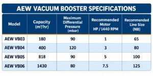
22. Application Selection Checklist
☐ Required operating pressure clearly defined in absolute units
☐ Required minimum pressure defined
☐ Required pump-down time defined
☐ Total process gas/vapour load calculated
☐ Air leakage/outgassing considered
☐ Condensable and non-condensable fractions identified
☐ Process and vapour temperatures identified
☐ Condenser duty and temperature identified
☐ Booster location selected: pre-condenser / post-condenser
☐ Backing pump type and capacity identified
☐ Booster suction pressure and differential pressure checked
☐ Required pumping speed verified from AEW performance curve
☐ Pipe diameter and pressure loss checked
☐ Liquid carryover protection provided where necessary
☐ Materials of construction and seal compatibility verified
☐ Motor/VFD/control philosophy defined
☐ Area classification and safety requirements verified
☐ Maintenance access provided
☐ Final GA/P&ID reviewed and approved
23. Customer Technical Enquiry Sheet
| Customer / Company: | |
| Application: | |
| Process: | |
| Product / Material being processed: | |
| Required vacuum — normal: | |
| Required vacuum — minimum: | |
| Initial pressure: | |
| Required pump-down time: | |
| Gas load: | |
| Water vapour load: | |
| Solvent / process vapour load: | |
| Air leakage / estimated leakage: | |
| Process temperature: | |
| Condenser temperature: | |
| Cooling-water temperature: | |
| Existing backing pump: | |
| Existing pump capacity: | |
| Existing pump ultimate vacuum: | |
| Booster installation location: | |
| Required operating hours: | |
| Batch / continuous: | |
| Electrical supply: | |
| Area classification: | |
| Special material / seal requirement: | |
| Available space / footprint: | |
| Customer P&ID / GA drawing: | |
| Additional notes: |
24. Glossary of Vacuum Terminology
| Term | Definition |
| Atmospheric pressure | Pressure exerted by the surrounding atmosphere; standard atmosphere is approximately 760 Torr. |
| Absolute pressure | Pressure measured from perfect vacuum. |
| Backing pressure | Pressure at the discharge side of a booster / suction side of the backing pump. |
| Backing pump | Fore pump that receives gas from the booster and exhausts it from the vacuum system. |
| Blank-off vacuum | Ultimate pressure approached by a pump under specified test conditions with the useful pumping load essentially removed. |
| Booster | A pump installed in series with a backing pump to increase pumping speed and/or improve attainable vacuum. |
| Compression mode | Booster arrangement in which the booster compresses gas before the backing pump. |
| Compression ratio | Discharge absolute pressure divided by suction absolute pressure. |
| Conductance | Ability of a pipe or component to pass gas under vacuum conditions; low conductance creates pressure loss. |
| Differential pressure | Discharge pressure minus suction pressure across the booster. |
| Foreline | Piping between the booster discharge and backing pump inlet. |
| Leak load | Unwanted gas entering a vacuum system. |
| Outgassing | Release of gas or vapour from materials and surfaces inside a vacuum system. |
| Pumping speed | Rate at which gas is volumetrically removed at a specified pressure and location. |
| Pump-down time | Time needed to reduce system pressure from an initial value to a specified final value. |
| Torr | Vacuum pressure unit approximately equal to one millimetre of mercury. |
| Throughput | Gas flow expressed as pressure × volume per unit time, or mass flow depending on context. |
| Vapour pressure | Equilibrium pressure of a vapour above its condensed phase at a specified temperature. |
25. Why Choose a Mechanical Vacuum Booster System?
A vacuum system should be evaluated by the process result it delivers—not simply by the nameplate capacity of an individual pump. A correctly engineered booster system can combine high volumetric displacement with a suitably sized backing pump to achieve faster evacuation, deeper working vacuum and improved process productivity.
For process industries, this can translate into shorter cycle times, improved drying or evaporation rates, better temperature control, improved vapour recovery and more effective use of existing vacuum equipment.
AEW engineering approach
- Understand the process and its vacuum requirement.
- Quantify the complete gas and vapour load.
- Evaluate condenser and piping limitations.
- Select the booster and backing pump as one system.
- Select the correct seal, materials and cooling arrangement.
- Define the control and protection philosophy.
- Verify the operating point against the AEW performance data.
- Provide a complete, maintainable and safe vacuum solution.
| Customer message AEW Mechanical Vacuum Boosters are engineered to enhance the performance of vacuum systems where high pumping speed and improved low-pressure operation are critical to process efficiency. |
